Part:BBa_K1761001:Design
Outer Membrane Protein X (OmpX) with BamHI-linker and mNeonGreen
- 10COMPATIBLE WITH RFC[10]
- 12COMPATIBLE WITH RFC[12]
- 21INCOMPATIBLE WITH RFC[21]Illegal BamHI site found at 574
Illegal BamHI site found at 619 - 23COMPATIBLE WITH RFC[23]
- 25COMPATIBLE WITH RFC[25]
- 1000COMPATIBLE WITH RFC[1000]
Design Notes
The sequence is redesigned considering codon optimalization. Also restriction sites for biobricking and classical cloning are deleted. From the BamHI linker, the coding sequecne for GGSGGS is redesigned causing that only two BamHI restriction sites remain.
Source
OmpX is a outer membrane protein naturally occuring in wildtype E.coli. The BamHI linker is inspired by the article "Quantitative Understanding of the Energy Transfer between Fluorescent Proteins Connected via Flexible Peptide Liners" by Toon H. Evers et all from 29 August 2006. mNeonGreen naturally occurs in the organism Branchiostoma Lanceolatum.
The Protein OmpX
For detailed information about the protein, we refer to part BBa_K1761000 [1].
The BamHI Linker
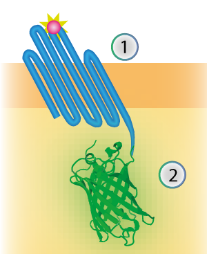
The linker connects the outer membrane protein with the signaling component (see Figure 1). The flexibility is generated by creating a linker consisting mostly of the amino acids Glycine and Serine.
Figure 1: Schematical overview of the expressed OmpX (1) with mNeonGreen (2) in the outer membrane of E.coli.
The Signaling Component
Two well-known principles to translate a close proximity into a measurable signal are Resonance Energy Transfer and the use of split luciferases (see Figure 2). Even though these principles are very different, both response elements emit light, yielding a measurable signal. After ligand binding, these signaling components yield a virtually immediate response.
Figure 2: Resonance energy transfer (A) and split luciferases (B) both translate close proximity into a measurable signal in the form of light.
Resonance Energy Transfer is a physical process which can take place between fluorophores light emission when they are in close proximity (1-10 nm) [1]. An electron which has been transferred to its ‘excited state’ falls back to its ‘ground state’. The energy which is released by the electron falling back to its ground state is normally released in the form of light. In the case of Resonance Energy Transfer, however, the energy of the electron falling back to its ground state is not released in the form of light, but coupled to a transition of an electron in the RET Acceptor to from its ground state to the excited state (see Figure 3).
Figure 3: Simplified energy-level diagram of RET. A) Normally, an excited electron falls back to its ground state under the emission of light (a radiative transition). B) In the case of Resonance Electron Transfer, an excited electron in the donor falls back to its ground state. This transition is coupled to the excitation of an electron in the acceptor. This excited electron falls back normally under the emission of light.
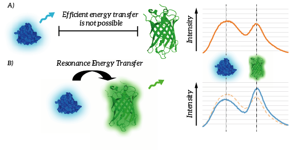
The efficiency of Resonance Energy Transfer is known to be dependent on a few factors, most importantly the relative orientation of the chromophores as well as the mutual distance of the chromophores [1]. A decreased mutual distance between the donor and acceptor increases the efficiency very significantly. This feature of Resonance Energy Transfer is exploited in the design of our membrane sensor. As a result of the reduced distance between the RET-donor and RET-acceptor, Resonance Energy Transfer is thus more efficient. As a result, relatively more light will be emitted by the acceptor when the ligand is bound. The resulting signal is thus, per definition ratiometric. As a result of ligand binding, intensity of the light emitted by the donor will decrease and intensity of the light emitted by the acceptor will increase (see Figure 4).
Figure 4: A) Efficient energy transfer is not possible since the donor and fluorophore are to remote. B) Efficient energy transfer is possible due to the proximity of the donor and acceptor. As a result, light intensity of the donor decreases whereas light intensity of the acceptor increases.
References
[1] I. Medintz and N. Hildebrandt, Eds., FRET - Förster Resonance Energy Transfer. Weinheim, Germany: Wiley-VCH Verlag GmbH & Co. KGaA, 2013.


